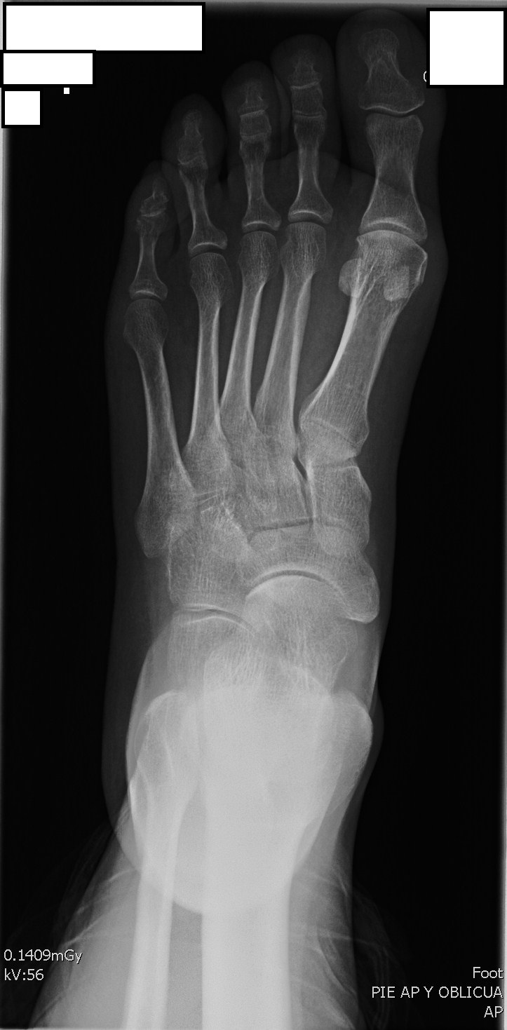
AP FOOT PROJECTION
Anteroposterior • Dorsoplantar View • Complete Foot Evaluation
Exposure Factors
Equipment: Without bucky. Position: Supine or seated.
Note: Low mAs due to low bone density of the foot
Plate Size
CENTERING POINT
Central anatomical point of the foot for precise centering
Anatomical Regions of the Foot
Forefoot
Phalanges and metatarsals
Midfoot
Cuneiforms, cuboid and navicular bones
Hindfoot
Talus and calcaneus
Visible Anatomical Structures
Phalanges
Distal, middle and proximal
Metatarsals
1st to 5th metatarsal
Tarsal Bones
Cuneiforms, navicular, cuboid
Talus and Calcaneus
Hindfoot bones
- Interphalangeal joints - Distal and proximal
- Metatarsophalangeal joints - Base of the toes
- Medial and lateral malleolus - Distal portion of tibia and fibula
- Cuneiforms - First, second and third
- Navicular bone - Tarsal scaphoid
- Talonavicular joint - Between talus and navicular
- Cuboid - Lateral tarsal bone
- Talar head - Anterior portion of talus
- Fifth metatarsal process - Peroneal tuberosity
- Calcaneocuboid joint - Between calcaneus and cuboid
- Calcaneus - Heel bone
- Distal part of tibia and fibula - Including malleoli
- Joint spaces - All foot joints
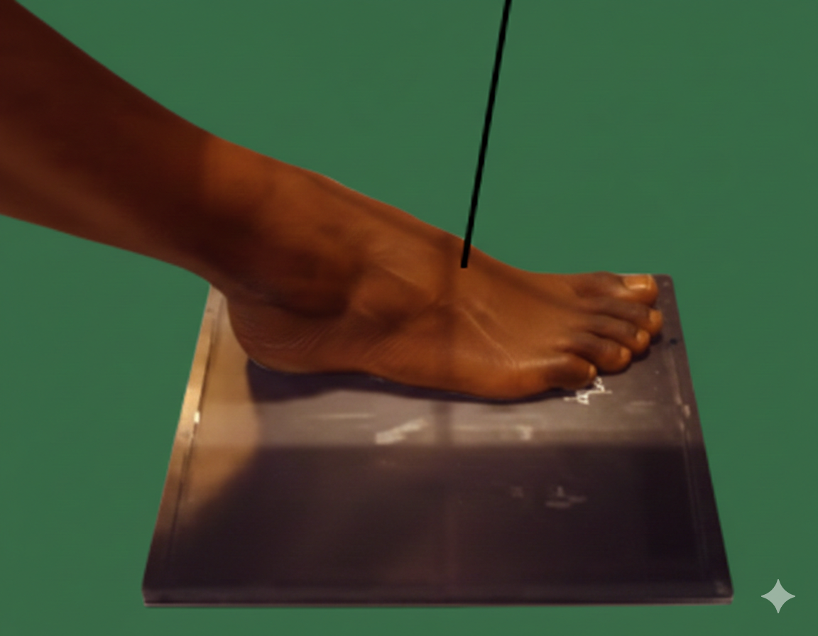
10° CEPHALIC ANGULATION
The central ray should be angulated cephalically about 10° directed to the base of the third metatarsal.
This angulation allows:
- Better visualization of joint spaces
- Reduction of bone overlap
- Optimal visualization of all foot bones
Patient Positioning
Central Ray Direction
Directed to base of third metatarsal with 10° cephalic angulation
Anatomical point: Base of third metatarsal
Angulation: 10° cephalic (towards head)
Entry point: Dorsal foot, approximately at mid-midfoot
Exit point: Plantar, at level of longitudinal arch
Goal: Complete visualization of all foot bones and joints
Patient Instructions
"Do not move during the examination"
Keep foot completely still - Toes supported on plate without moving
Technical Considerations
10° Angulation
Cephalic angulation essential for optimal joint visualization.
Axis Alignment
Precise alignment between cassette axis and longitudinal foot axis.
Complete Contact
Sole of foot with toes fully supported on cassette.
Clinical Indications
Image Quality Criteria
Complete Visualization
All foot bones from toes to heel visible
Joint Spaces
Joint spaces open and without overlap
Correct Alignment
Foot axis aligned with cassette axis
Radiological Study of the Foot
COMPLEMENTARY PROJECTIONS
AP foot projection is typically complemented with:
These three projections allow three-dimensional evaluation of the foot
Special Technical Note
LOW MILLIAMPERAGE (4-10 mAs)
The foot requires very low mAs (4-10 mAs) due to:
- Low bone density - Small and thin bones
- Little soft tissue - Minimal X-ray attenuation
- High sensitivity - Images easily overexposed
- Fine detail required - Visualization of small structures
Adjust mAs according to foot size and patient age (children require even less)